Slave Box 2 wiring

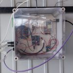
Intro Slave Box 2 wiring

The owner of the house lost the remote controllers which was paired to the opener throughout the years. Now it seems he cannot by these old controllers anymore so he had two options. Buy a new opener which would be very costly or find a solution to use newer remote controllers. Obviously we went to implement the second option. This is now we arrived at today’s topic which is Slave Box 2 external radio board wiring to Exitec garage opener. 


Investigation

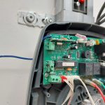
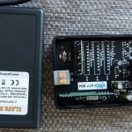
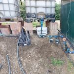
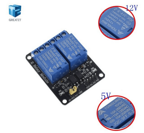
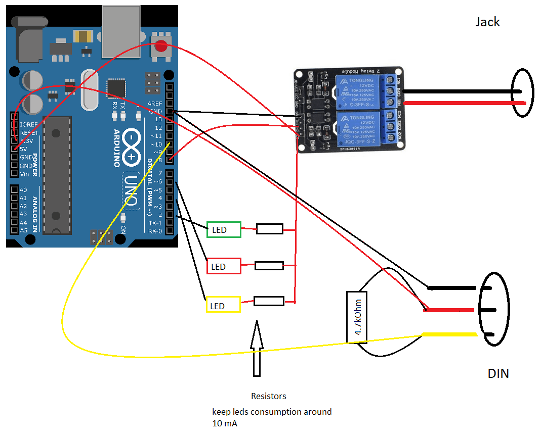
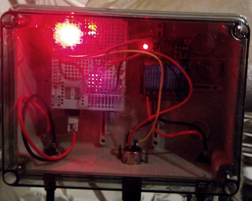
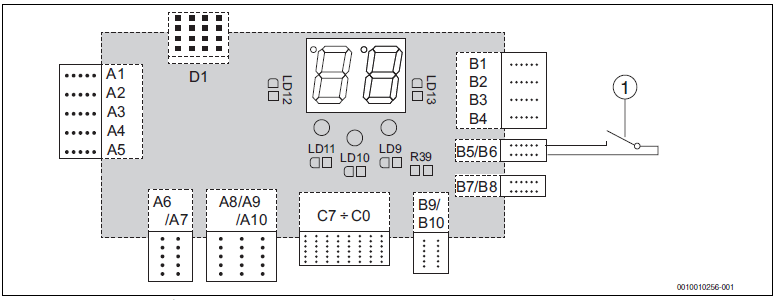
When we opened the main unit of the garage opener we realized there is no exact ports, connections or other possibilities to hook on. The Slave box 2 requires input power to work and it has 2 NO/NC connector to use. This is what we needed to combine somehow to make our customer happy. Of course all the time when we need to do something like this we are very carefully measuring all ports, connectors voltages and write them down.

Solution Slave Box 2 wiring

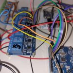
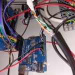
After the initial investigation we tried to find relevant wiring and installation how to manuals. After several hours of searching without luck it turned out that there is no information available online. Right here would like to say “Thank you!” to all the installers whom we were able to reach as they were so kind and helped us with their expertise. So the solution is the following:
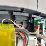
  • keep all the hooks/loops as if you remove them the gate will not work.
  • you can safely get the power from the infra port
  • you can use the gate port ground leg to have a signal which can be “transmitted” via the Slave Box 2 relay legs.
  • you need yo use proper wire size as the ports are not designed to handle thick wires.
 

External Links:

DIY Garden automation controller – Final Part

DIY Garden automation intro

In our previous post we showed what where the steps during the process of making our DIY garden automation controller. If you have not read them we highly recommend to read those entries. But back to track: in this entry finally all the components got connected and the first tests where conducted.


Investigation

We encountered several bumps just when we thought there is no more surprise will arise. First it turned out there the desired place of the water tanks are lower then the surface we would like to irrigate. So as you can see we have to move 2m3 dirt to have the right surface at the right place.
The final most ‘unwanted’ issue turned out to be the connection issue. The 2.4Ghz signal was not reaching our main Wifi router. Let’s solve this issue 🙂


Solution

So the connection issue. We tried several approach but nothing helped… After a few devastated minutes we realized that in our shelf we have a Wifi antenna which was brought to a different project but it has not been used. Let’s use it. Of course the male/female SMA connectors were not matching 🙁 Pfff … this is not good. Then again! We had some smd to SMA connectors in some of our boxes. We had luck and find one which made the connection possible. With the usage of a laser pointer we managed to mount the antenna correctly and we had signal!

DIY Garden automation tests results and future improvements

This is the lists where we have room for improvements:
  • The water level sensor can get ‘clogged up’ which results in incorrect readings. this is caused by the scale and the algae
  • It is highly recommended a physical water level detector just like with the submerged pumps because that’s more reliable
  • electricity goes through water obviously but it means that one of your cheap can generate unwanted-faulty ground connection [flow sensor]
  • Do not be afraid to use Google
 

DIY Garden irrigation controller – Part III

Intro

We are happy to introduce the completed DIY Garden irrigation controller. It was a long time ago since we started to work on this project. Looking at the timestamps its really shocking how much time passed. Anyhow now it is completed and ready to server it’s purpose and will help us to grow amazing vegetables. We also need to admit that this is only the ‘brain’ of the hardware so the electric wiring and fuses still need to be installed. For that we will have a separate entry. Now let’s jump into the hardware details! Also if You are interested in the previous entries please check out : part II

 Quick recap

DIY Garden irrigation controller contains the following main parts:

  • Wemos pro mini
  • Arduino Uno
  • Relay board
  • Power supply
  • DC-DC converter

As a quick recap – we need the Wemos pro mini for the communication with the Wifi network and also for uploading the data for cloud so we can monitor the system via the internet. Arduino Uno is needed because we needed a lots of pins for relays and also for detecting water level in our water tank.

Explanation

For our well we needed to add a bit more complex shutdown procedure as the pump is old and grumpy. It means if you disconnect it under load [when it is pumping water] it sends back a huge voltage spike to the grid which is not good, also if you pull it from the plug it will create a huge spark… For this reason we added a flow sensor to monitor when the well runs out of water the pump stops on its own. We can get 100L in every 3 minutes then for ~10 minutes we do not have enough water in the well. This is the time window when we can shut down the pump. Everything else it’s quit straightforward. We also have a gray water tank which we use to water the grass which has a submerged pump in it,  we trigger it during dawn. Have a motorized ball valve for starting the irrigation and one extra option for switching on a lamp.

Code is available here : github link

DIY Garden irrigation controller

Which so many others project this Wifi DIY garden irrigation system was not completed in time for the season. On the software side we reached 95% readiness and well on hardware side we had a little bit of a delay. We physically have everything what we need. The components on their own been tested ad they are ready to build in. But, there is always a but! The place of the controller and the planned 230V setup was not completed in time. Because of this there was no reason to rush with the controller… It will be ready for the next season! 🙂 Till then a few images how it will be assembled in its container and deployed to the field.

Who did not read the first entry can do it here : first steps – Wifi DIY garden irrigation

diy garden irrigation control box
servo controller ball valve
flow detector attach to KPE pipe

Bosch Tronic Heat 3500 18kw electric heater puffer tank thermostat

This is the story of the creation the Bosch Tronic Heat thermostat:

We installed a Bosch Tronic Heat 3500 electric heater. After it was successfully installed we faced the following problem:

  •  in pump in the unit was working continuously which is required so it can measure the current water temperature
  • unfortunately this keeps all the piping on the same  temperature as the fluid itself
  • no matter how hard we tried to insulate the them it will always ‘leak’ a bit so we lose energy in the basement
  • the solution could be that the pump only works when the tank really need to be warmed up
  • our current thermostat controls that part of the heating system which pulls the water from the tank into the heating pipes in the building so we cannot use that
  • reading articles on the internet we came to a conclusion that we need a thermostat for the heater itself
  • we did not find anythings in the local shops or on the net or we were not really impressed with their price and service pairing, so we created one
  • the signal circle is a simple 24DC ‘short-circuit’ on the heater side
  • we put the sensor on the puffer tank exist connector which goes to the heater and covered it with some  thin foil and some stone-wool
  • sensor showed us exactly the same values as on the physical gauges mounted on the side of the tank so we think it was positioned and insulated correctly.
The implementation is not complicated and the used components are widely available.
The total assembly can be done in 4 hours.
 
The completed unit images can be found the gallery below.

Arduino source code: github-link

Links:

This was the story of the creation of Bosch Tronic Heat thermostat.

‘Houston we have a problem!’ – Improvise from what you have

It always strange when time does not fly like the Millennium Falcon in hyperspace then it seems to be no moving. In the next second you realize that you already late with your own ‘I want to do that!’. My plan was to create a controller for my plants so I can water them automatically which free up some time up my end and would guarantee that the plants will not dry out if I’m not around for a few days. Everything went smoothly, I was thinking on the how and with what questions. Then suddenly the calendar shows me it almost summer and I’m nowhere with the controller. Panic mode ‘ON’ let’s see what we have in house, what we can improvise. I quickly pulled together the previous project’s leftovers to see what we can use. It is always a good idea to order more then you need from the given parts, accessories etc. making sure you have spare parts or sooner later a decent own stockpile.

Stayed tuned! Next post is coming soon!

project leftovers

Wifi Heat Controller

This DIY Wifi Heat Controller is easy to build and have a lot of potential for further imporvements.

We have an electric heater, but it need a controller which can give a signal to it. Would be good if we can use low budget components to minimize the cost. We should be able to controller it without being physically close to the device.

During the phase when we were discussing what we really like to have, it came up that checking the state of the unit from all our the globe would be magnificent, so the user can to a vacation and still knows that everything goes fine at home.  

So how we solved this issue of Wifi Heat Controller? Check it below:

Used building components:

  • wemos mini pro because it have external antenna which makes the Wifi signal much better
  • relay board with 4 relays
  • ds1862 temperature sensor

Description:

  • the received data from the sensor is collected and an avarage is calculated
  • if the value goes under the predefine value relay 1 will be switched on
  • relay 1 turns on the heating unit which start to operate
  • other relays can be used for optional actions
  • controlling the unit is doable via the mini web server which runs on the device
  • the unit can be updated over wifi
  • data can be uploaded to the cloud, so the user can check them anywhere
  • in the cloud you just need to a simple endpoint which is capable of receiving data can show it in the way you imagine it. 
Room for improvements:
– summer mode is not tested, but will be interesting to see when it starts it action
– error led added later which is not visible on the images to show the user that is has issues with Wifi connection, but it just hangs there which is not too elegant

– when 230V AC will be switched using the relays the casing can be dangerous 

Link to source code of the DIY Wifi Heat Controller

Wemos Wifi Heat Controller
Wemos Pro Heating Controller with Relay Board

Need any help? Contact Us!