Solar street light repair

Solar street light repair intro

We bought a two new solar street light which we planned to mount on the street front of our property. After reading the manual it recommended to put it to direct sunlight for a day or two to make sure the battery will be charged. Unfortunately the batteries fried themself and we had no lights anymore this is where our solar street light repair story begins.

Investigation

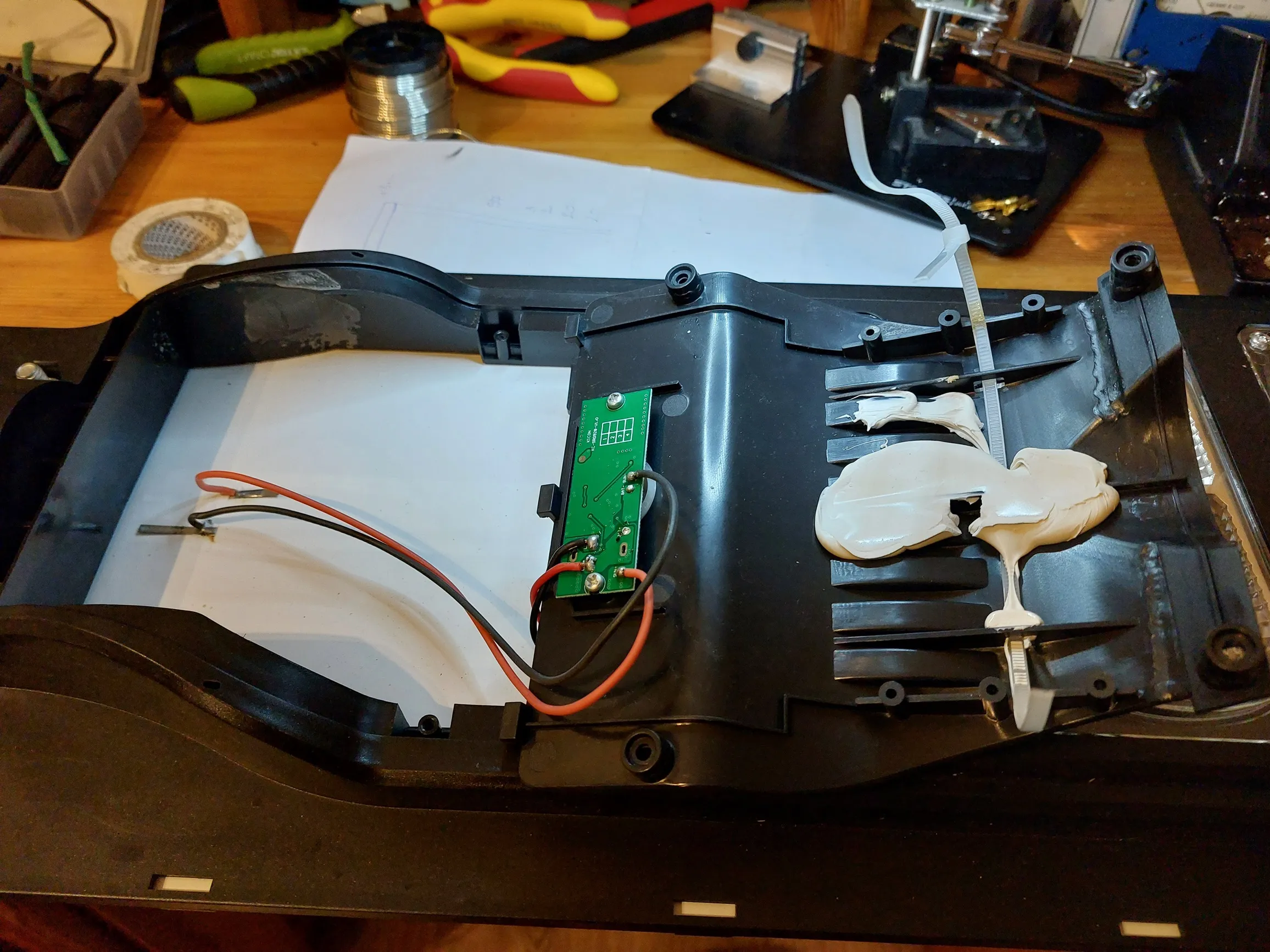
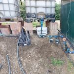
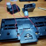
After disassembling the unit it revealed its secret. The LiFePO4 battery “ran out” of juice literally and now it was showing short using a multi-meter. As we have lots of space in the lamp we decided to create a new battery set from our remaining 18650 cells.

Solution

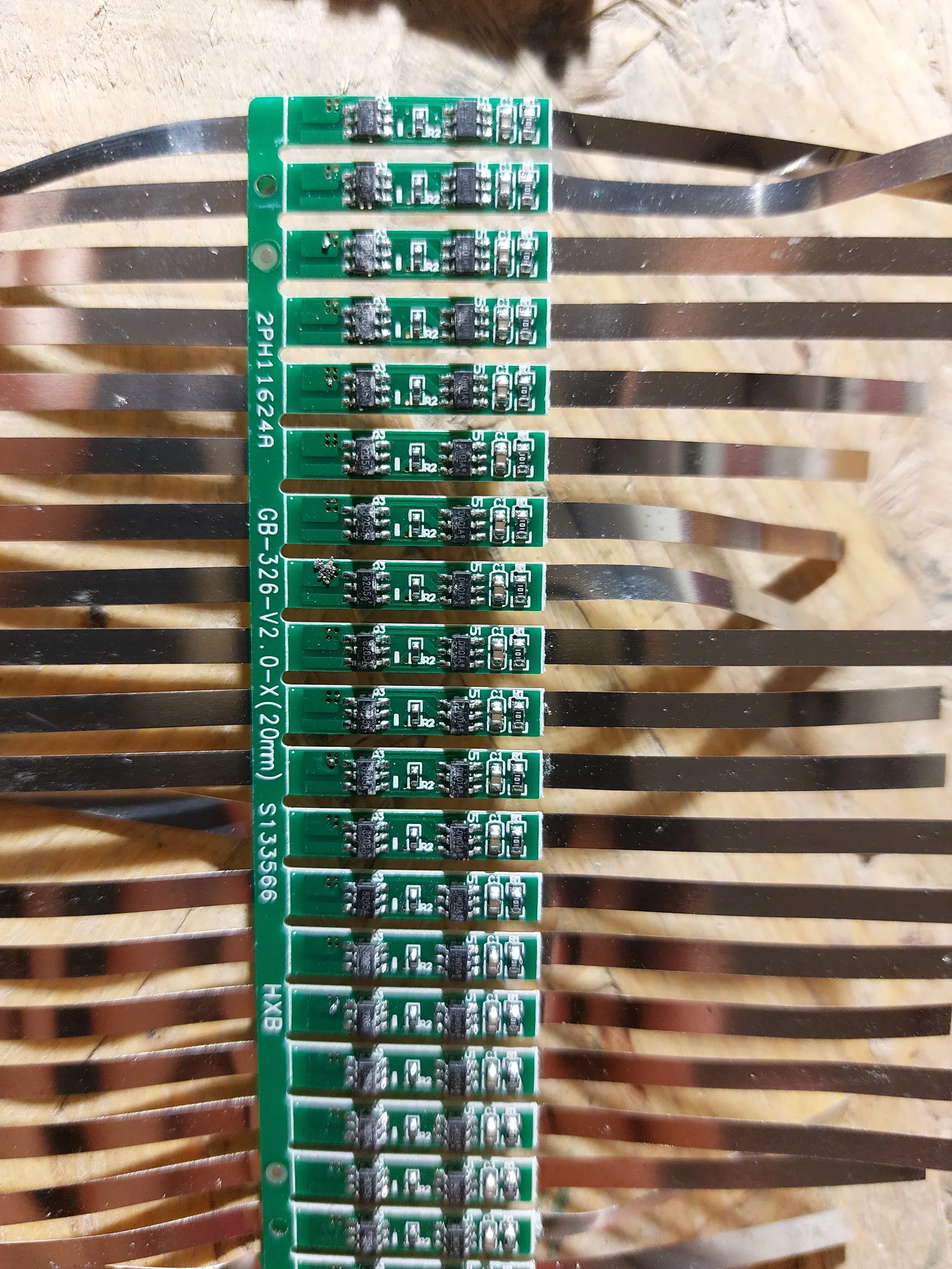
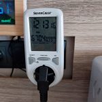
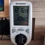
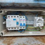
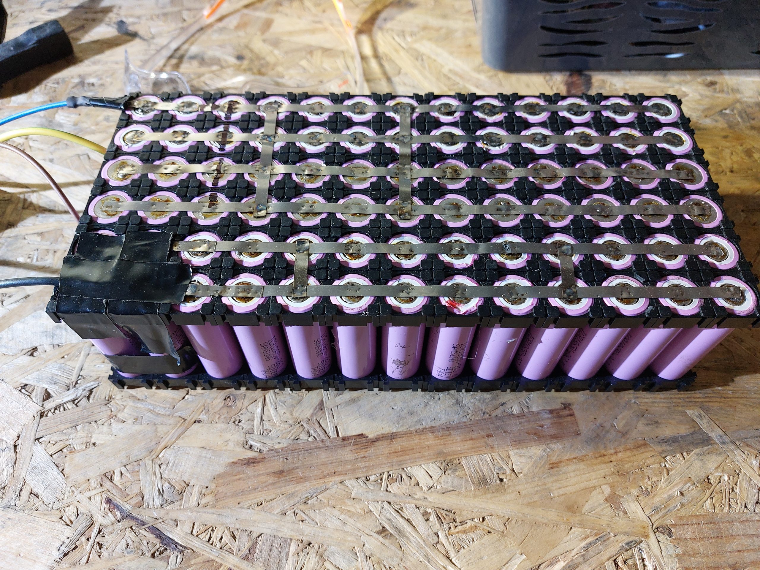
We took our remaining cells and created a super huge capacity battery so our solar street light can light all now long even during the long winter nights. We created a 2S Li-Ion battery pack using BMS to make sure we will not over or undercharge the cells. We had this idea after we have measured the short voltage value of the solar cells. This was a mistake! The solar cells produce less voltage when they are under load… So after we created our battery pack we faced two issues: – we created a bigger pack and it did not fit [we forgot to calculate the size of the plastic holder] – the battery pack provided more voltage then the circuit was needed. Yes your are right we fried the PCB! 🙁

Solar street light repair tests results and future improvements

We have the following open topic:
– when disassembling something do not through away parts till you took photo of them. Even if they are leaking batteries
– do some test with labor power supply unit to make sure about the operation voltage of the system
– the lamps do not work
– we do not have a proper battery
– do not be afraid to use Google
– we did not solve the issue 🙂

DIY Garden automation controller – Final Part

DIY Garden automation intro

In our previous post we showed what where the steps during the process of making our DIY garden automation controller. If you have not read them we highly recommend to read those entries. But back to track: in this entry finally all the components got connected and the first tests where conducted.


Investigation

We encountered several bumps just when we thought there is no more surprise will arise. First it turned out there the desired place of the water tanks are lower then the surface we would like to irrigate. So as you can see we have to move 2m3 dirt to have the right surface at the right place.
The final most ‘unwanted’ issue turned out to be the connection issue. The 2.4Ghz signal was not reaching our main Wifi router. Let’s solve this issue 🙂


Solution

So the connection issue. We tried several approach but nothing helped… After a few devastated minutes we realized that in our shelf we have a Wifi antenna which was brought to a different project but it has not been used. Let’s use it. Of course the male/female SMA connectors were not matching 🙁 Pfff … this is not good. Then again! We had some smd to SMA connectors in some of our boxes. We had luck and find one which made the connection possible. With the usage of a laser pointer we managed to mount the antenna correctly and we had signal!

DIY Garden automation tests results and future improvements

This is the lists where we have room for improvements:
  • The water level sensor can get ‘clogged up’ which results in incorrect readings. this is caused by the scale and the algae
  • It is highly recommended a physical water level detector just like with the submerged pumps because that’s more reliable
  • electricity goes through water obviously but it means that one of your cheap can generate unwanted-faulty ground connection [flow sensor]
  • Do not be afraid to use Google
 

How to use summer surplus solar energy

Intro

During summertime we face surplus solar energy as solar systems produce most of their annual production. We can often hear that it generates surplus energy in the grid which is hard to deal with based on industry experts. In this entry we would like to demonstrate how we can ‘mitigate’ this with some pre-thinking. We know that it will not change the world, but one example which can be get used to.


Investigation

With all the effort we put into our automated garden know we see the results. It will be shown in a different post but in a nutshell we have plenty of vegetables. We cannot consume all of it and we would like to preserve them in a way which does not use energy at all, or requires much less. Running a freezer all year around is an energy hungry activity if we would like to minimize out footprint. What can be done to fulfill both goals. Follow us to the solution section to see what we can up!


Solution for surplus solar energy

Most of the vegetables cannot be stored for months so we need to preserve them. One option is to store them in the freezer and the other is to create canned food from it. The issue with canning, boiling and baking that they lose lots of their ‘value – content’. Then we realized there is a third option with is drying. With that the vegetables only losses their water content but based on the books the keep their ‘real’ value. So we ordered a tray drier to preserve. Yes this is only for a few months but if you can still taste the tomatoes, cucumber etc in a middle of December that is a huge win. As you can  see our drier uses 600w when the heater is on and 10W when its standby. Using the highest value 600Wx24h means we used approximately 14kwh. Is it much? We will make a few more rounds then draw the consequences!
 
Thank you for your attention staying with for our surplus solar energy entry!

DIY garden irrigation controller – Part IV – wiring

Intro

Our project arrived to a stage were its needs electrical work this is called: DIY garden irrigation wiring. The backbone of automation is the hardware which is capable of serving the need of the software. We were thinking a lot how we can assemble the control box which contains all the switches and relays what we need but remains as simple as possible. In this blog entry you will see what is the idea we came up with and how we implemented it.

Investigation

The most important when working with electricity is safety so we started to investigate the main fuse box. It turned out that in our test environment the original electrical wiring was rusted and not functioning properly. The RCD braker was totally jammed! Immediately the complete subpanel was rebuilt and then we tested the life saver component with a resistor. Please keep in mind that this step operates with deadly voltage so don’t do it if you don’t know what you are doing! Next we investigated our load components ans found out that we only need 16A so we used the proper main size fuse. When the new setup was complete in the subpanel we moved to the controller box.

Solution for  DIY garden irrigation wiring

As our pump needs to run 5-8 hours per day to deliver the required amount of water to our tanks we thought a simple relay would not be sufficient. So we used an impulse relay to control the well pump.
 For the submerged pump which needs to run 15-20 mins every second day we kept a simple 230V relay. Of course all of our equipment have its own circuit braker so we can disable them if needed. The box with the microcontroller also received its own as in case of software failure we can still operate the pumps.
 
That would be all for today! Stay tuned next parts coming soon as DIY garden irrigation wiring was not the last entry for this job!
 
Code is available here : github link

Repairing card shuffler #ReduceElectronicWaste

Intro

In this post we are a bit diverted from our main focus, but we feel this is an important topic which worth it. We would like to share our experience in repairing a card shuffler #ReduceElectronicWaste. In these days people tend to throw away electronic devices without any hesitation.

Investigation

So let’s dive into the details! After removing the screws and opening the device we again realized that simplicity rules :)! The two battery holder which are holding the four AA battery are wired in series and they are just soldered on the motors terminals. In the middle there is a push switch which can be operated by the user which is closing the gap between the battery holders and that is it. Then if it that simple what could go wrong? Well we assumed the the motors are operational so we did not check them one by one. We started to investigate the power terminals of the motors and realized that no power is provided to the terminals. Hmmm nice that is something! Using a multi meter we started to measure voltages on the battery holders. Wow! None of the compartments terminals have actual voltage… Investigating further we realized that there is no contact between the batteries and the holder so not even inside the compartment we have a ‘circuit’. We have found the root cause!

Solution

 We used a little screwdriver to bend the terminals within the battery holder so they touches the relevant side of the AA battery. After double checking that both holder has voltage on their terminal we gently pushed the button. Viola we have a working unit! In 20 minutes we were able to repair / fix it and now we completed repairing a card shuffler #ReduceElectronicWaste. Please try to consider repairing everything which you could to reduce our impact on the environment!
 
Have a nice day!

Back to Blog page.

DIY Garden irrigation controller – Part III

Intro

We are happy to introduce the completed DIY Garden irrigation controller. It was a long time ago since we started to work on this project. Looking at the timestamps its really shocking how much time passed. Anyhow now it is completed and ready to server it’s purpose and will help us to grow amazing vegetables. We also need to admit that this is only the ‘brain’ of the hardware so the electric wiring and fuses still need to be installed. For that we will have a separate entry. Now let’s jump into the hardware details! Also if You are interested in the previous entries please check out : part II

 Quick recap

DIY Garden irrigation controller contains the following main parts:

  • Wemos pro mini
  • Arduino Uno
  • Relay board
  • Power supply
  • DC-DC converter

As a quick recap – we need the Wemos pro mini for the communication with the Wifi network and also for uploading the data for cloud so we can monitor the system via the internet. Arduino Uno is needed because we needed a lots of pins for relays and also for detecting water level in our water tank.

Explanation

For our well we needed to add a bit more complex shutdown procedure as the pump is old and grumpy. It means if you disconnect it under load [when it is pumping water] it sends back a huge voltage spike to the grid which is not good, also if you pull it from the plug it will create a huge spark… For this reason we added a flow sensor to monitor when the well runs out of water the pump stops on its own. We can get 100L in every 3 minutes then for ~10 minutes we do not have enough water in the well. This is the time window when we can shut down the pump. Everything else it’s quit straightforward. We also have a gray water tank which we use to water the grass which has a submerged pump in it,  we trigger it during dawn. Have a motorized ball valve for starting the irrigation and one extra option for switching on a lamp.

Code is available here : github link

LoRa Gateway GPS Tracker

For a long time now we were planning to build something which uses LoRa technology. For one of our coming project we needed to create a Proof of Concept to test various available components from the market. What can be more useful for validating range specifications then a GPS Tracker which bring all this together. This is why we built this LoRa Gateway GPS Tracker.

Process of building and testing: First we built two unit using the E220 modules to test the example codes we found on the internet. Luckily as expected there were a tons of example. wiring diagrams, video tutorials about the topic. The issue we ran into that some schematics were not correct and it took a while to realize that this is not our fault. One of our main information source was : mischianti.org . As it is mentioned several places you need to be careful when “marrying” microcomputers on different voltage levels on their I/O interfaces. In one of our dis-assembly phase during debugging and error chasing phase we accidentally missed a voltage regulator between an Arduino Uno and the E220 module which has a very bad result on the module life cycle. R.I.P. e220 module! We also realized we need more test breadboard as they speed of a POC cycle a lot. When you work with Wemos mini, mini pro or with D1 models it makes it more easy as their communication voltage level is 3.3V. Please also keep in mind that these communication modules transmit in various frequencies with adjustable transmission power so be aware of the local regulations! That was our first part for LoRa Gateway GPS Tracker as the range test will be published in a separate blog entry whenever the weather makes it possible.

Do It Yourself battery pack

We were planning to create a DIY battery from 18650 cells for our off-grid project for a long time but as always low priority experimental tasks have to wait. The goal was to reuse some 18650 cells from previous builds to test their capability and be environment friendly. We also wanted to create the biggest battery that would fit in the box for obviouse reasons, and before I forgot we wanted to created a 12v battery pack.Let’s see what we have created in our free time!

We prepared for a build with the followings:

  • 18650 cells
  • Charge controller
  • Nickel plated steel belt
  • 12V car battery charger
  • test load device [a car h4 bulb with 65W which requires ~5A]

These are the steps we did:

  • we charged / test all the cells so make sure we have the same condition cells in one series
  • with this information we were able to determine which cells were not usable
  • then we packed them in a group
  • we used our spot welder to weld the nickel belt to a series
  • then one by one we connected to the series to each other carefully making sure no short will happen
  • soldered the charge controller to the battery pack
  • tested the load and charge process
  • tested the load and charge process with 10 times the current which we will need
  • tested the balancing option within the charge controller by cycling the battery and checking the voltage level of each pack[in the series] within the battery

Summary of our  DIY battery from 18650 cells:

  • we completed the task without any major issues 🙂
  • we were able to created a 65Ah battery which is huge
  • it fits into the required space with the plastic holders [they were not counted…]
  • with this capacity, we estimate that our device can operate for three weeks without having any sunshine

Back to blog page.

DVR image uploader – Wemos mini pro

We were thinking about a DVR image uploader using a Wemos mini pro for while. Wemos pro can do Http Https calls as well. We wanted to solve the following issues. Let assume you have a DVR which is monitoring your property. To reach the images from a remote location you need access the DVR main unit somehow. There are many options available like VPN server, using DNS and open ports etc. but they were not in sync with our expectations. We did not wanted to have a running VPN server although it’s a pretty fast solution and recommended by many. We did not wanted to open ports for security reasons especially for a device which does not get firmware updates frequently or at all. This was our initial setup. Let’s see what we did till we found the solution.

Seeking the solution:

The most convenient was to use a raspberry PI with a small application which extracts the images from the DVR and uploads it to the cloud where remote access is possible. We encountered some issues here as well. First one of our cornerstone was compromised as the raspberry requires an UPS to make sure it does not crash during the first power outage. Second the documentation how we can access the DVR content was not easy to find. We spent many hours finding searching for examples and documentation. Finally we found something which tried out using Postman and it worked. After that creating a java console application was not a big deal. Everything worked fine except that we needed to run the PI. There needs to be a better solution! 🙂

Implementation with Wemos pro using Http Https:

DVR image uploader using a Wemos mini pro with 16MB flash has the capability to send Http and Https messages. The question was can it handle ‘large’ data objects due to it’s memory limitations. We tried to download the images to all kind of variable formats but all of them exceeded the Wemos mini pro capabilities. Then we decided to use the option which comes with this micro computer. Let’s save the content to files the read from there so we do not need all the memory in the same time. We struggled a lot but finally we managed to complete the project. It pulls the images using http from the DVR and saves them to its internal drive.

Final steps:

Then using Https post it to the cloud where we have a very simple PHP interface which can receive it. We are using a simple html file to display the images! Project completed! 🙂

Back to blog page.

Source code available on github.

Soldering issues wemos pro mini

Today’s topic will be the soldering issues with wemos mini pro. When dealing with today’s micro electronics even on entry level these components can be really small. On one side it is good as you can have a lots of memory and computing capacity in a tiny place but is also means when you have to modify / fix something you have to have a stable hand and a very good pair of eyes. Even if you do you can still ran into issues which we would like to show you in this post. We were working on a very simple proof of concept and we were in a rush to deliver it. Everything was ready on ‘table’ meaning that you probably familiar with. All components wired together software is working correctly BUT you still need to pack it somehow to deliver and test it in its desired location.

Realizing we haven an error

When we completed packing / boxing and conducted a final test the
project was not functioning anymore. Huuuuuh – big hale and exhale. What
is the first question which goes over our head? Is the wiring got
broken? Is the hardware got damaged? No not these 🙂 The first which
comes out from your mouth is : “Why it has to happen with me?”

Finding the root cause

Then you start to disassemble the POC wire by wire and checking the outputs. Of course two things can happen during this process: the last connection which you are going to double check will be the issue, or none of them. So no matter where you start it will take long time. When our board had no connections we came to a conclusion that it has to be soldering issues. So we took our microscope and started to examine the soldering points. On image 1-2 you can see the legs where we had the soldering issues on the wemos mini pro . The soldering material was not running all the way down to the panel which caused the connection error.

Finally we could assemble the project and move on!